 QFH Antenna (The Quadrifilar Helical antenna)
provides circular polarization
and complete hemispherical reception, which is precisely what is needed to
receive the polar orbiting weather satellites, and as a 2 meter antenna it
will receive
horizontal, vertical and clockwise circular polarization’s from all directions.
Fig 1. illustrates the antenna which consists of two vertical loops at right
angles to each other, resonant at slightly different frequencies, twisted into
a half turn helix.
Correctly made it will provide true all round coverage with circular
polarization at all angles.
The usual crossed dipoles and reflectors used for satellite reception only
provide circular polarization
directly upwards when the signal strength is high anyway, at low angles when
maximum
sensitivity is required the polarization is linear, losing 3 dB on the
circularly polarized
satellite signal. In addition Quadrature feed of crossed dipoles to achieve
circular
polarization is beautiful in theory and almost impossible to achieve in
practice.
QFH Antenna (The Quadrifilar Helical antenna)
provides circular polarization
and complete hemispherical reception, which is precisely what is needed to
receive the polar orbiting weather satellites, and as a 2 meter antenna it
will receive
horizontal, vertical and clockwise circular polarization’s from all directions.
Fig 1. illustrates the antenna which consists of two vertical loops at right
angles to each other, resonant at slightly different frequencies, twisted into
a half turn helix.
Correctly made it will provide true all round coverage with circular
polarization at all angles.
The usual crossed dipoles and reflectors used for satellite reception only
provide circular polarization
directly upwards when the signal strength is high anyway, at low angles when
maximum
sensitivity is required the polarization is linear, losing 3 dB on the
circularly polarized
satellite signal. In addition Quadrature feed of crossed dipoles to achieve
circular
polarization is beautiful in theory and almost impossible to achieve in
practice.
Bob Cobey G0HPO an avid weather satellite fan first made one in this area and reported phenomenal results, even inside the roof space of his bungalow. Good noise free pictures were received from Greenland through to Algeria.
The R.I.G articles by Mark Pepper Rig 37 and Chris Van Lint (Rig 44) and also in QST are based on the original work by NASA featured in the ARRL Antenna handbook. There are a number of practical problems in the design which have been addressed and solved over many weeks of computer modelling and prototype construction.
 The computer generated (Azimuth & Elevation) polar diagrams are of course
perfection and a series of actual measurements of the horizontal and vertical
patterns were undertaken on the final design to confirm the computer results.
The computer generated (Azimuth & Elevation) polar diagrams are of course
perfection and a series of actual measurements of the horizontal and vertical
patterns were undertaken on the final design to confirm the computer results.
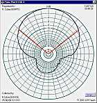
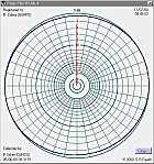
The measured vertical and horizontal polar diagrams using clockwise polarization, were produced using the latest version of a program by Bob Freeth ( G4HFQ ) called PolarPlot. The Windows 95/98 & 2000 version of the program is now available for download by visiting his page using the links in the right hand column.
Vertical and horizontal polarization’s are 3dB down on clockwise
as expected and the horizontal pattern is still circular.
The polar diagram in the vertical plane is particularly useful, showing very
little reception from below, thus reducing the formation of nulls caused
by ground reflections.
 There are no nulls in the horizontal pattern at any polarization. Allowing for
slight distortion in actual measurement of antenna performance, caused by the
usual site problems the measured plots and measured gain were identical to the
computer generated
plots which was particularly satisfying, given the inherent difficulty in
modelling a helix in XYZ format
for the computer.
There are no nulls in the horizontal pattern at any polarization. Allowing for
slight distortion in actual measurement of antenna performance, caused by the
usual site problems the measured plots and measured gain were identical to the
computer generated
plots which was particularly satisfying, given the inherent difficulty in
modelling a helix in XYZ format
for the computer.
The major problem is how to make the beast, and particularly how to make it
weatherproof.
Firstly the dimensions given by the NASA based articles need to be adjusted for
weather satellite and 2 meter frequencies. The diameter of tubing used in the
ARRL
handbook works out to 19mm at 137 MHz and dimensions show the INSIDE diameter
of the helix.
Conversion to 8mm tubing which is a much more sensible size at 137 and 145 MHz
was not just a question of simple scaling. As stated in the book a
quadrature-phase
current relationship is required between the two loops. This is achieved by
making one loop larger
than the desired frequency resonant length and therefore inductive, while the
other loop is smaller and therefore capacitive. Correct resonance of each loop
means that
a circular pattern may be achieved by simply connecting the two loops in
parallel. This is
confirmed in practice when the SWR dips once only at the required frequency. It
is all too easy to get a double hump response which is incorrect, and will show
a figure
of eight pattern rather than a true circular horizontal polar diagram. The
sizes shown
have been confirmed by computer modelling and actual measurements on the
prototype, and do not conform with the book figures. In particular the helix
should be the
same diameter throughout its length and therefore the length of the arms
forming the helix is important.
The formula for this length is
![]() where 'r' is the radius and 'h' the height of the helix.
where 'r' is the radius and 'h' the height of the helix.
 The major problem was how to make weatherproof the connections at top and
bottom of the helix. The connections at the top of the helix in the original
design were
almost impossible, as the connection had to be made to the ends of four tubes,
two of which were 24mm below the top two, with all inside the support mast.
Using the computer modelling program, various connection methods were tried to
establish a sensible method without compromising the performance. It proved
possible to slope the tops of the small loop so that all four tube ends were in
a common
plane at the top of the mast where they can be reached.
The final method uses a small piece of PC board very simply made, shown in
Fig 2, which gives good mechanical and electrical connections.
The major problem was how to make weatherproof the connections at top and
bottom of the helix. The connections at the top of the helix in the original
design were
almost impossible, as the connection had to be made to the ends of four tubes,
two of which were 24mm below the top two, with all inside the support mast.
Using the computer modelling program, various connection methods were tried to
establish a sensible method without compromising the performance. It proved
possible to slope the tops of the small loop so that all four tube ends were in
a common
plane at the top of the mast where they can be reached.
The final method uses a small piece of PC board very simply made, shown in
Fig 2, which gives good mechanical and electrical connections.
 Fig 3 illustrates the original infinite balun arrangement which provides an
elegant way of bringing the feeder away from the antenna at a voltage null.
This is totally impossible to make if the antenna is made using a central non
metallic
support mast (as it must be at 137 MHz) when the connections would have to be
made
inside the mast.
Fig 3 illustrates the original infinite balun arrangement which provides an
elegant way of bringing the feeder away from the antenna at a voltage null.
This is totally impossible to make if the antenna is made using a central non
metallic
support mast (as it must be at 137 MHz) when the connections would have to be
made
inside the mast.
One solution to this was to make the antenna from two continuous lengths of
copper tubing with a small diameter coaxial feeder brought through a hole in
the feed tube at the null point and connected at the top. This would still be
difficult
as the feeder entry hole would be inside the support mast. In practice moving
the hole
a few millimetres to bring the feeder outside the mast solves the mechanical
problem and since
the current in the lower half of the loop is substantially constant, still
provides a good
enough voltage null to get the feeder away without affecting the performance of
the
antenna. The outer braiding of the coax need not be connected to the tube at
the point of
exit thus preserving the integrity of the coax for weatherproofing. Several
antennas were
built using this method and were perfectly satisfactory electrically, but
construction was
extremely difficult. Various methods of actually making the Helix were tried,
the use of
coaxial cable as in previous designs is acceptable as an indoor antenna but
weatherproofing for
outside use is almost impossible. 8mm soft copper central heating tube
available from the
plumbing department of all DIY shops and builders merchants proved to be the
easiest to use. Bending tubing by hand is not satisfactory unless the resulting
kinks and
flattening are acceptable. The elegant way is to use small copper elbows at the
corners
but it proved totally impossible to insert RG58 coax into the tube after the
elbows had been
sweated into position and sweating after the coax was inside was not a good
idea.
 While the original balun design is perfection electrically, it is the main
cause of the construction difficulties, and some other type of balun was
required. The use of a simple choke balun proved to be the answer and solved
all the mechanical problems.
While the original balun design is perfection electrically, it is the main
cause of the construction difficulties, and some other type of balun was
required. The use of a simple choke balun proved to be the answer and solved
all the mechanical problems.
Fig.4 illustrates the feed method where the necessary isolating choke
is formed from winding 4 turns of the feeder cable round the support mast. No
longer does the antenna have to be constructed from coaxial cable or have
coaxial cable threaded through tubes, and it CAN BE MADE with identical
performance to the original NASA design. Performance checks comparing the
original design with
the new system showed no differences, in particular the feeder was still dead.
CONSTRUCTION
 Fig.5 shows the final design using 8mm copper tube with dimensions shown as cut
lengths for 137.55 MHz allowing for the length of the copper elbows.
Any change in tube size will require different dimensions. Make no mistake, the
dimensions are important. This antenna will work after a fashion with almost
any slip shod
construction but then the polar diagram will not be circular and its a matter
of luck whether
the maximum lobes are in a useful position.
Fig.5 shows the final design using 8mm copper tube with dimensions shown as cut
lengths for 137.55 MHz allowing for the length of the copper elbows.
Any change in tube size will require different dimensions. Make no mistake, the
dimensions are important. This antenna will work after a fashion with almost
any slip shod
construction but then the polar diagram will not be circular and its a matter
of luck whether
the maximum lobes are in a useful position.
 Mark out the plastic support mast using the template Fig 6 to ensure that the
holes are at right angles. Drill the 4 x 8mm holes, two at the top at
right angles in the same plane and the two lower down at right angles spaced
24mm. Then drill the 7 mm hole near the top of the mast for the cable
entry as shown in fig 4.
Mark out the plastic support mast using the template Fig 6 to ensure that the
holes are at right angles. Drill the 4 x 8mm holes, two at the top at
right angles in the same plane and the two lower down at right angles spaced
24mm. Then drill the 7 mm hole near the top of the mast for the cable
entry as shown in fig 4.
Carefully straighten the roll of 8mm tube. This is best done by rolling it out
onto the floor keeping the coil vertical. Cut the tube into lengths to the
dimensions
shown and drill the appropriate holes for the self tapping screws in the ends
of the top horizontal sections.
Firstly make the top part of the antenna with the cable and connections. Feed
the coax through the hole into the mast and then out of the top threading it
through the
hole in the centre of the PC board. The top 4 horizontal tubes can then be
assembled, the
two horizontal tubes forming the top of the smaller of the two loops should be
carefully bent
24mm see Fig. 7.
 The PC board should be mounted copper side down to connect with the copper of
the tubes, thus avoiding any dissimilar metal problems with the possible zinc
plating of the screws.
Four turns of the feeder cable should now be wound around the support mast to
form the balun and taped into position.
The PC board should be mounted copper side down to connect with the copper of
the tubes, thus avoiding any dissimilar metal problems with the possible zinc
plating of the screws.
Four turns of the feeder cable should now be wound around the support mast to
form the balun and taped into position.
Next mount the lower 2 horizontal sections through the mast positioning them
centrally.
The helix can now be formed. First place the copper elbows into position but do
not solder at this stage. Carefully bend the appropriate lengths of tube to
form the helix. Remember the helix should be wound ANTICLOCKWISE as seen from
the top
(and the bottom for that matter) to provide clockwise polarization as used on
the weather
satellites. Final soldering into place can now be done using a small gas torch,
the plumbers’ trick of applying flux to the copper tubes before fitting onto
the elbows will
ensure quick and easy flow of solder.
The connections at the top require an end cap for weatherproofing and although
the appropriate pieces can be obtained from the same source as the plastic tube
the user may well find a plastic jar cover of suitable size to do the job.
Cut lengths in mm for 137.55 MHz, using 8mm Central Heating tube & 90 deg elbows.
|
|
|
|
|
|
|
|
|
|
|
|
|
|
|
|
|
|||
|
|
|
|
|
|
|
Parts List (Cost less than Ł15 from most Hardware Stores)